
This simple, easy-to-build mount provides the perfect introduction to long-exposure astrophotography.
Round stars. That’s the difference between astrophotos captured with a camera that tracks the sky’s motion versus one that doesn’t. Traditionally you’d make a tracked photo by placing your camera piggyback on a telescope with a motorized equatorial mount. But that’s a lot of equipment to deal with if all you want are some nice-looking constellation portraits or a shot of a newly discovered comet — especially if you have to travel to reach your favorite dark-sky destination.

The mount described here provides one of the easiest ways to track the night sky with your camera. Known generically as a barn-door tracking platform, it’s easy to make and works well for camera-and-lens astrophotography. I built the tracker shown here based on one recently made by Ohio telescope maker Ed Jones and on a platform built by Sky & Telescope’s Dennis di Cicco in the mid-1980s. Ed and Dennis used parts they had lying around, but I used components sourced online and from local hardware stores.
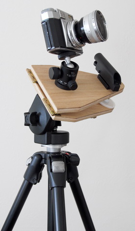
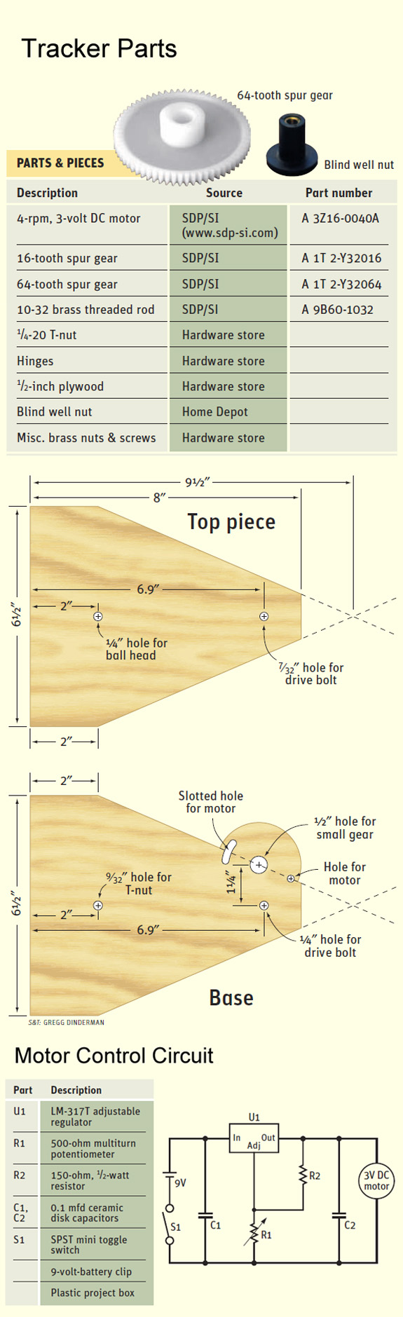
As the parts diagram at the end of this article shows, the tracking platform consists of two triangular pieces of plywood joined along one edge by a pair of hinges that serve as the mount’s polar axis. Your camera attaches to the top piece via a photographic ball head (available at any camera store), while the bottom piece (the base) mates to an ordinary camera tripod.
The tracking action comes from raising the top plate at a precise rate. This is accomplished with a motor, a pair of spur gears, and a curved length of threaded brass rod. The only tools needed for this project are a jigsaw, drill, screw-driver, and soldering iron.
Construction Details
Begin by cutting the two wooden parts from ½-inch-thick plywood. These pieces are almost identical — the hump to accommodate the motor on the base is the main difference. The only critical dimension is the distance between the hole for the threaded rod and the center of the hinge pins. This must be as close to 7.14 inches (18.1 centimeters) as you can make it. In my mount, the hinge pins hang off the end of the base by almost ¼ inch, which is where the 6.9-inch dimension in the plans comes from (6.9 + 0.24 = 7.14). If the hinges you purchase are different, you’ll need to adjust the length of the boards accordingly.
Next, drill the necessary holes in both wooden parts. Note that the distance between the holes for the motor shaft and the drive bolt is 1¼ inches. (If you choose a different motor and gears, this spacing may change.) To allow the two gears to mesh properly, one of the motor-mounting holes is slotted to provide a little room for adjustment.
The other hole that needs special attention is the one on the base board that the curved drive bolt goes through. To avoid binding, you want the bolt to pass through as thin a layer of wood as practical. Use a ½-inch Forstner or spade bit to countersink a hole in the underside of the base board to a depth of about ⅜ inch. Drill the rest of the way through with a standard ¼-inch bit.
After you drill all the holes, give the wood parts a protective coating. I used MinWax paste finishing wax, but any suitable paint or polyurethane will do. Finally, insert the T-nut into the bottom board and attach the hinges.
Bending the Drive Bolt
For the mount to track accurately, it needs a curved drive bolt. But how do you make an accurate bend in a length of threaded rod? Ed Jones described a simple method in which he drew the required curve on a piece of paper taped to a flat surface. Next, he placed the threaded rod onto the paper and gradually bent it until the curve in the rod matched the one drawn on the paper.
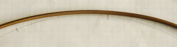
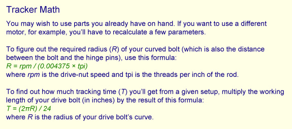
For my mount, the radius of the required curve is 7.14 inches. However, you need to subtract half the thickness of the threaded rod from this dimension for the curve to match the inside radius of the bend. A 7-inch-radius curve is close enough for this purpose. Because it’s difficult to evenly bend a short length of threaded rod, start with a piece that is at least 1 foot long. Once you’ve achieved a good curve of the correct radius, use a hacksaw to cut out a 4- or 5-inch-long section — choose the piece that most closely matches the desired curve. A segment of this length will yield around 1½ hours of uninterrupted tracking.
Attach the drive bolt to the mount’s top board with an acorn nut, lock washer, and flat washer on the top side, and a plain nut and washer underneath. At this point you’ll likely find that the bolt doesn’t pass cleanly through the hole in the base. Simply grasp the threaded rod near where it attaches to the top board and gently bend it a little until it goes through the hole without scraping or binding.

A key part of the assembly is the drive nut, which couples the large gear to the threaded rod. I used a blind well nut (shown below) purchased at my local Home Depot (and available form numerous online sources, as a Google search will reveal). A 10-32 nut glued with two-part epoxy to the underside of the gear should work as well.
Prepare the gear by inserting the blind well nut and trimming off the rubber flange. I had to enlarge the hole in the gear slightly with a round file for a good friction fit. If you choose to glue a nut to the underside of the gear instead, make sure that the nut is accurately centered over the hole. The easiest way to do this is to use a spare 10-32 bolt wrapped with a few strips of paper or masking tape so that it fits snugly into the hole. Thread the nut into place and apply the glue, making sure you don’t get any epoxy on the threads. Once the glue has set, carefully unscrew the bolt and remove the paper strips. Thread the assembly onto the drive shaft and en-sure that it turns smoothly.
Next, slip the small gear onto the motor’s drive shaft, and attach the motor to the bottom board with nuts and bolts. Adjust the height of the small gear until it’s even with the main drive gear, then lock the set screw. Pivot the motor until the two gears engage properly, and tighten everything down.
The Drive and Electronics
The motor used in this design turns at 4 revolutions per minute (rpm). It’s a 3-volt DC gearhead motor manufactured by Hankscraft (model 3440-3V). You’ll need a pair of gears to reduce the motor’s speed to 1 rpm. I used a 16-tooth gear attached to the motor and a 64-tooth gear driving the nut on the threaded rod. Most of these parts are available from a wide range of sources. Mine were purchased from Stock Drive Products/Sterling Instruments (SDP/SI). If you decide to use a motor that turns at a different rate, you’ll need different gears to achieve the required 1 rpm. You also have to make sure there’s enough clearance between the motor housing and the drive bolt so the latter doesn’t collide with the former.
One nice feature of the DC motor is that its speed depends on the voltage of the power supply — a precise and constant voltage is all it takes to ensure accurate tracking. The voltage-regulator circuit shown in the diagram below is easy to build and allows you to fine-tune the motor’s speed to precisely 1 rpm. The components aren’t particularly exotic, and you should have no trouble getting them from a local electronic- parts store or online from places like Mouser Electronics or Digi-Key.
My regulator circuit is housed in a plastic project box and uses a standard RCA-type jack to connect to the motor. Note that the positive and negative leads are reversed from those shown on the motor. This is to ensure that the motor runs counterclockwise, which is the correct direction for use in the Northern Hemisphere. (Photographers in the Southern Hemisphere users will want the motor to run clockwise.) If the motor runs the wrong way, the tracking platform is literally worse than useless!
Testing and Using the Tracker
Before attempting your first photograph you have to adjust the motor speed so that the large gear turns at exactly 1 rpm. The easiest way to do this is to mark one of the gear’s teeth with a felt pen and add a small tick mark to the base. Run the motor, and start your stopwatch just as the marked tooth aligns with the tick. After exactly one minutes, stop the motor and see where the marked tooth is relative to the index mark. (For increased accuracy, let the motor run for two to five minutes.) Adjust the multiturn potentiometer and repeat the test until you get the motor running at the correct speed.
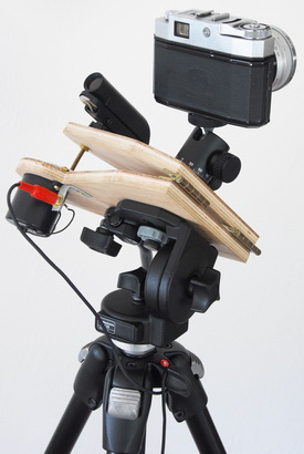
To use the tracker, place it atop a camera tripod and sight along the hinge pin to aim the mount at Polaris. As the photos show, I use a red-dot finder for polar alignment, though this is more a matter of convenience than accuracy. You could also use a finderscope or, as Ed Jones does, a laser pointer. In situations where I cannot see Polaris, I use a compass and inclinometer to set up the mount — the compass to adjust the mount in azimuth, the inclinometer to match my location’s latitude.
Once the mount is polar aligned, you should switch on the motor and let the drive run for a minute or so before opening your camera’s shutter. This allows things to settle down and enables the motor to take up any slack in the drive.

Although a curved-bolt barn-door camera platform is a simple piece of equipment and easy to build, it can produce excellent results, as this phto of Orion shows.
After shooting for a while, you’ll notice that the drive gear needs to be reset. This is easy to do. Switch off the motor, lift the top board so that the two gears disengage, and spin the drive gear counterclockwise until it is back near the top of the curved bolt. Gently lower the top board back into position (taking care to ensure the gears mesh), and resume shooting.
I’ve found this tracker to be the ideal photographic plat-form for travel. So far, it’s accompanied me on numerous trips. including visits to Costa Rica and to the Mt. Kobau Star Party. Since it’s so lightweight and takes up so little room in my suitcase, there’s really no reason not to bring it along.
Note: This is an updated and expanded version of an article I wrote for the June 2007 issue of Sky & Telescope magazine.
Did you find this article interesting or helpful? If so, consider using this link the next time you shop at Amazon.com. Better yet, bookmark it for future use. Thanks to Amazon’s associates program, doing so costs you nothing yet helps keep this site up and running. Thanks!