

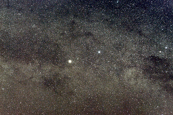
This image of the Scorpius Milky Way was captured from Costa Rica with a DSLR camera and the simple hinge tracker mount described here.
If you have a DSLR camera and are interested in astronomy, you’ve probably considered dipping a toe into the astrophotography waters. But a camera is only part of the equation — for exposures longer than a few seconds, a tracking mount is usually necessary. Unfortunately, most suitable mounts are relatively bulky, or expensive, or both. But not the hinge tracker. It costs less than $10 to build, takes less than an evening to assemble, and requires no batteries. And best of all, you can put one together even if you’ve never built anything more complicated than Ikea furniture.

The hinge mount is assembled from a handful of common hardware-store items and requires no machining. In addition to the tracker, you’ll need a photographic ball head and a regular camera tripod to complete the setup.
Parts Roundup
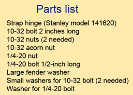
The heart of my tracker is a heavy duty, 8-inch strap hinge made by Stanley Hardware. You can use any brand — the crucial parameter is the distance from the centre of the hinge pin to the centre of the hole at the far end of the hinge, which should be close to 7-3/16 inches (182mm). You’ll also want to choose a hinge that has minimal play. This is why I like the Stanley model — the nylon bushings between hinge halves provides a smooth running, sturdy assembly. When you’re at the hardware store, try a few out and pick the one that feels best.
The second important part is the drive screw. It needs to have 32 threads-per-inch, or the mount won’t track at the correct rate. I used a 2-inch-long, 10-32 brass screw for my mount, but a stainless-steel screw will work just as well. You’ll also need a few other bits of hardware, which are given in the parts list above. None of these items are exotic; you should be able to get everything at your local hardware store and walk out with change from a $10 bill.
Assembly
The first step in assembling the hinge tracker is to glue one of the 10-32 nuts to the hole farthest from the hinge pin, and the ¼-20 nut to the lower of the two holes nearest the pin — both go on the inside face of the lower hinge wing, as shown in the photo below. The small nut is for the drive screw, while the other one allows you to attach the mount to your camera tripod. It’s important for the drive screw to bear against a flat surface, so you need to glue the large fender washer to the underside of the top hinge wing such that it covers the hole farthest from the hinge pin.
I tested several adhesives for this project, but the only one that worked well was a two-part epoxy called J-B Weld, suggested by my S&T colleague Dennis di Cicco. Not only does J-B Weld bond metal-to-metal, it’s readily available and easy to work with. When you glue the nuts, do your best to make sure that they’re centred over the appropriate holes and that no glue ends up on the threads. J-B Weld takes hours to cure, so you have lots of time to reposition the nuts to get them into exactly the right place.
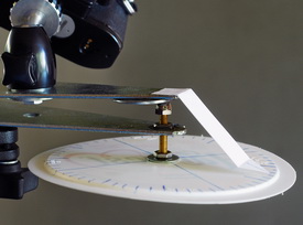
The next step is to assemble the drive mechanism. This utilizes some of the hardware you purchased along with a drive wheel you have to make. The wheel for my tracker is a 6½-inch-diameter plastic lid from a margarine container. I trimmed off the lid’s lip with a X-ACTO knife, making the lid relatively floppy, which is a good thing — you don’t want to jiggle the mount whenever you touch the drive wheel. By using a flimsy piece of plastic, you ensure that only rotational motion is efficiently transferred to the drive screw.
Use a permanent marker and a protractor to make tick marks on the outer edge of the disk every 6°, with every fifth tick drawn a little longer than the rest. You’ll be turning the wheel once every minute, so each tick corresponds to one second. Make a hole in the centre of the wheel for the drive screw to fit through. (Look for a small dimple that marks the exact centre of the lid.)
The last piece to make is the pointer. I used a scrap piece of plastic from the margarine container, cut to shape with scissors. Bend the pointer into a stretched out “Z” shape, and use double-sided tape to attach it to the top wing of the hinge. This placement keeps that the spacing between the pointer and the wheel constant as you turn the drive screw.
After the epoxy hardens, you’re ready for final assembly. Run the 10-32 drive screw through the centre of the plastic wheel, installing a washer on either side. Thread on a nut and tighten everything down so that the wheel is firmly clamped between the washers. Next, thread the drive screw onto the mount from the underside, then screw on the acorn nut. Lastly, run a ½-inch-long ¼-20 bolt through the washer and the top half of the hinge and into the base of your camera’s ball head.
Polar Alignment
Before you can start taking pictures you have to align the mount with the north celestial pole. For most purposes, simply sighting along the hinge to aim at Polaris will provide sufficiently accurate polar alignment. However, if you want to be more precise, use the following procedure:
1. Set up your mount with the hinge pin on your left when you’re facing north, and use the tripod’s pan/tilt adjustment to aim the hinge pin at Polaris.
2. Centre the star in the camera’s viewfinder by adjusting the ball head.
3. Swing the camera through 180° by lifting the top half of the hinge and observe the arc that the star traces in the camera viewfinder.
4. Use the ball head to tweak the camera’s position until it’s pointed at the centre of the circle that the stars traced in the viewfinder. This aligns the centre of the viewfinder with the rotational axis of the hinge.
5. Now adjust the tripod so the camera is centred on Polaris, and repeat steps 2 to 4 until it doesn’t appear to move when you perform step 3.
Alternatively, you can do most of this in daylight by using a distant landmark (instead of Polaris) to align the rotational axis of the hinge with the centre of the viewfinder. Then, at night, you simply aim the camera at Polaris by moving the tripod’s pan/tilt adjustment. Day or night, the entire process takes only a minute once you’ve done it a couple of times.
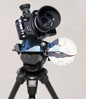
Using the Hinge Tracker
Once the tracker is polar aligned, aim your camera at your target by adjusting the ball head only. (Moving the tripod head will cause you to lose polar alignment!) To track the stars, you turn the drive wheel counterclockwise at a rate of one rotation per minute. You can monitor your progress by listening to a short-wave radio tuned to a WWV time signal, but I find it easier to simply record a few minutes of metronome beats (or time signal) onto my iPod, which I listen to with headphones.
The procedure for taking pictures is quite simple. Pull up a chair next to the mount and start your time signal. Open the camera’s shutter (a delayed shutter-release is very helpful for this) and begin turning the hinge mount’s drive wheel. In practice, you probably won’t have to turn the wheel in 1-second increments. If you’re using lens with a focal length of 50mm or less, you can move the wheel five tick marks once every five seconds instead. This reduces the chances of jiggling the mount. If you find trailing on pictures taken with longer focal-length lenses, turn the wheel more frequently.
The mount will track for about 10 minutes before its accuracy starts to decline due to “tangent error” caused by the straight drive screw. However, one of the benefits of a DSLR camera is its excellent high-ISO performance, which means you rarely have to take exposures longer than 2 or 3 minutes duration — and often less than that. You can achieve the equivalent of longer exposures by taking several short ones, and stacking the resulting frames together with software, such as the freeware program DeepSky Stacker. I have used lenses as long as 135mm focal length (which functions as a 200mm lens on my Nikon DSLR) on my hinge tracker and achieved fine results.
Several accessories will make your life easier. First, a remote control shutter release (preferably with an interval timer) is a real help. Second, if your camera doesn’t have a tilting view screen, a right-angle viewer that attaches to your camera’s optical viewfinder saves a lot of neck strain.
This simple hinge tracker won’t take the place of a more sophisticated mount, but for a quick and easy entry into astrophotography, it can’t be beat.
Meet the Mini Hinge Tracker
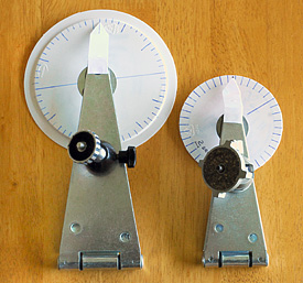
The standard hinge tracker is highly portable but you can make an even more compact version that will slip into any equipment bag as a “just in case” piece of gear. The basic construction is the same as with the original, but uses a 6-inch hinge in place of the 8-inch model. This change necessitates an important modification.
The tracker’s drive rate is set by three things: the distance from the hinge pin to the drive screw, the number of threads-per-inch of the drive screw, and the rate at which the drive screw turns. Obviously, changing the first of these means one or both of the other parameters must also change.
For my mini hinge tracker, I decided to stay with the original’s 10-32 drive screw, which means I could only compensate for the new hinge size by changing the rate at which the screw rotates — it could no longer run at the original’s ever-so-tidy 1 rpm. Calculating the correct rate (which worked out to be 0.735 rpm) was simply a matter of doing the math, but figuring out a way to run the tracker at that speed took more head scratching than I care to admit. The solution was to divide the drive wheel into 40, evenly spaced tick marks (one mark every 9°) and then to turn the wheel at a rate of one tick every two seconds. That produces a drive rate of 0.75 rpm, which is close enough to the perfect speed that the difference won’t matter.
The only other slight difference was that I had to use a smaller drive wheel to avoid contact with the tripod’s pan/tilt head. This part could be no larger than 4-inches diameter, bit its size has no bearing on the mount’s functionality.
Meet the Motorized Hinge Tracker
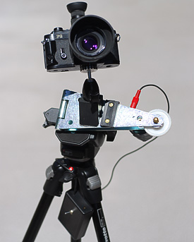
Although the hand-powered trackers are the simplest to build, if you’re handy with a soldering iron and have a little experience building telescope stuff, adding a motor and gears won’t tax your skills too badly. At its heart, the motorized version is essentially the same as the motorized barn-door tracker described here. The drive mechanism and motor-control circuit are identical. The main difference is that the body of the hinge tracker is just a hinge, so there aren’t any plywood parts to cut.
While it’s possible to make a bracket to attach the motor off to the side (where it is on my barn-door tracker), I chose to mount mine in-line for a more-compact assembly. As a result, the motor and curved bolt rubbed against each other, which is obviously not a good thing. I remedied this simply by filing down a bit of the motor’s plastic housing.
A second upgrade included in the motorized version of my hinge tracker is a camera-mounting block. This can be added to any of the trackers, and it really makes it easier to aim your camera’s ball head. Bolting the ball head directly to the hinge works fine, but it forces you to turn the camera over to access much of the sky north of the celestial equator. The mounting block shown here allows you to avoid that awkwardness. It’s made from a piece of 1½-inch hardwood stock, with one side cut to a 45° angle. I threaded a ¼-20 hanger bolt into the wood part, and then used J-B Weld to glue the block to the hinge.
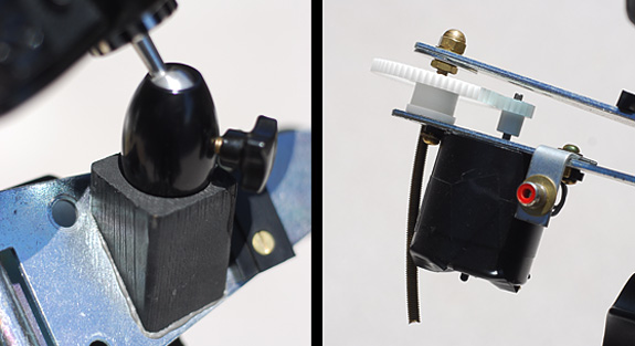
The motorized tracker’s ball-head mounting block (left) and drive assembly (right).
Any of these trackers will get you up and running taking sky photos with the minimum fuss and expense. And who knows — this might be the only camera mount your astrophotography ever requires!
Did you find this article interesting or helpful? If so, consider using this link the next time you shop at Amazon.com. Better yet, bookmark it for future use. Thanks to Amazon’s associates program, doing so costs you nothing yet helps keep this site up and running. Thanks!
This view of the star field surrounding Alpha and Beta Centauri was captured with a camera riding on the original hinge tracker.
(Note: This article is an updated and greatly expanded version of one that appeared in the August 2011 issue of Sky&Telescope magazine.)