
Day 8: Going Round in Circles
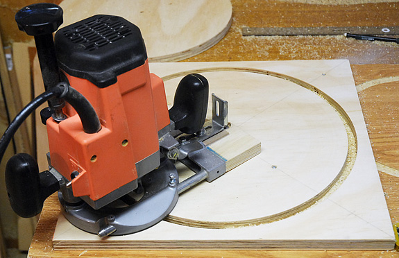
Routing the hole for the top of the mirror box.
Cutting neat, tidy circles in plywood. This is where a plunge router really shines. And make no mistake — building a Dobsonian means cutting circles. In the case of my scope’s design, the first ones are for the tube ring and for the flange at the back of the tube, where it mates with the mirror box.
It’s true that you can make these cuts with the jigsaw I described on Day 6, but it would be a bit tedious and time consuming. And it’s likely that the results wouldn’t be as pleasing. That said, unless you take the time to set up your router carefully, good results are not guaranteed.
For this kind of work, a plunge-type router (like this one) does an excellent job. My router didn’t come with a compass jig, so I had to cobble one together from spare hardware and some of the bits and pieces the router did come with.
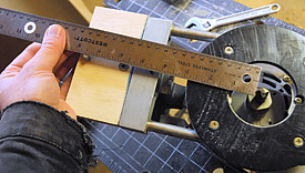
Setting the radius of the circle to be cut. Luckily I noticed before it was too late that I should have measured to the outside edge of the router bit!
Cutting circles is conceptually straight forward — you set up the router, clamp (or screw) down the work piece, and have at it. But a couple of lessons I learned the hard way are worth mentioning. First, never is the “measure twice/cut once” rule more important. There are lots of ways to cut a circle of the wrong diameter. I find it helpful to draw a circle that’s close to the desired size on the wood first. This way, if I’ve goofed up it should be pretty obvious when I set the router down. Indeed, this is exactly what saved me from making a serious blunder when cutting my tube ring. The way I nearly messed up was by measuring the radius of my circle from the pivot pin on my compass jig, to the inside edge of the router bit. What I actually needed to do was measure to the outside edge of the bit.
Another lesson is make your cut with several passes. Don’t try to go all the way through the wood in one go, unless you enjoy the smell of charred plywood. Even for the ¾-inch plywood I’m using here, I made four passes — each a little deeper than the previous one.
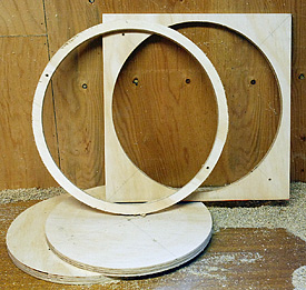
The result of an hour’s routing — a tube ring and rear flange piece.
It’s also important to make sure your work piece is secured. There’s nothing worse than having a piece of wood come loose midway through a cut. I put scrap wood under my work piece and screw down both the part I’m cutting out, and the wood I’m cutting from. That way, when I finally do get all the way through, nothing moves.
Finally, make sure the router’s cord is out of the way and that you can complete your entire circle without the router hitting a clamp or running over a screw. Just swing the router all the way around the circle once with the power switched off. You’d be surprised how often this will save you from trouble.
So at the end of my routing, I was pleased to get a tube ring of the correct inside and outside diameter, and cut a neat circular hole into the piece that will be the top of my mirror box. All without smoking up the workshop!
Day 9: Fixing a Hole
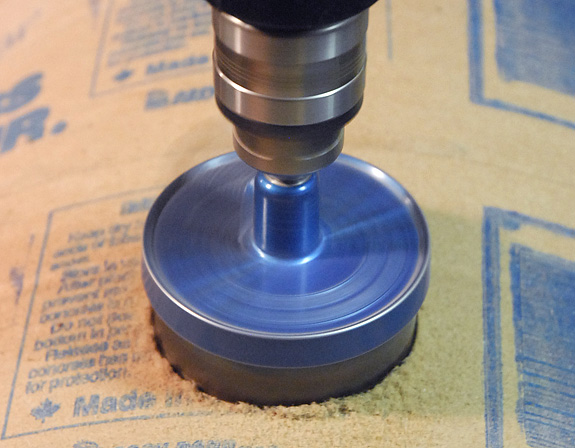
Using a hole saw to cut an accurate circle in the tube for the telescope’s focuser.
Cardboard tubing can be miserable stuff to drill neat holes in. The big hole needed for the focuser can be especially messy. Fortunately, there’s a little trick that really helps.
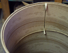
An extra length of tubing fit inside the telescope tube. Note the small wooden wedges.
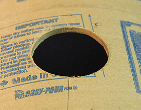
A nice clean focuser hole.
The key to getting clean holes is to use a backing, so that as the drill exits the cardboard on the inside of the tube, it doesn’t shred the innermost layer. Here’s what I did. I used the 8-inch long piece of scrap tubing left over from when I cut the scope’s tube to length. With the table saw, I slit the piece lengthwise. Next, I slid it into my tube and marked the overlap at the ends with a pencil. Finally, I cut the overlap off (plus a hair extra) so that the piece fit neatly inside the tube with about a ⅛-inch gap where the ends meet. (A jig saw works fine for these cuts too.)
I slid this piece into the tube so that it was positioned directly under where I planned on drilling holes. I inserted a pair of little wooden wedges where the ends of the scrap tubing meet, which forced the piece to conform snugly to the inside of my tube, as shown in the picture at right.
With the backing in place, I was able to drill the holes for the spider, focuser, and finderscope mount confident that the exit holes will be nice and tidy. Even the 2½-inch diameter focuser hole I made with the hole saw came out clean. It’s a small thing perhaps, but I find that taking care of little details like this to get good results makes the whole project a touch more satisfying.
As an aside, an insert can also be used to strengthen the tubes of smaller scopes. It’s especially useful at the front end of the tube, where the focuser, finder, and spider mount. Do all the steps outlined above, but apply a generous amount of wood glue to the outside of the insert before you position it. (Make sure to avoid getting glue on the wooden wedges, which you remove once the glue dries.) Since I’ll be using a plywood ring at the front of the 12¾-inch, there’s no need for additional reinforcement.
Day 10: Reinforcements
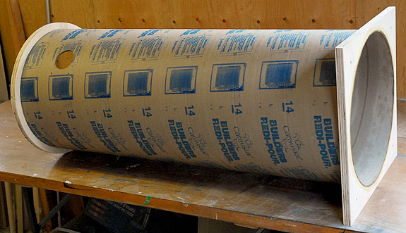
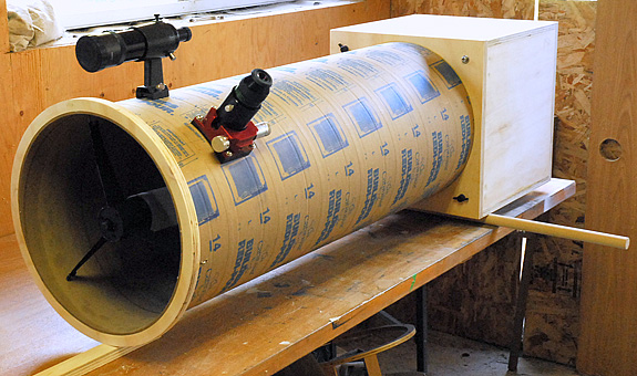
The upper tube assembly complete with front ring and rear flange.
Concrete form tubes have many characteristics that make them suitable as telescope tubes. They’re relatively lightweight, inexpensive, thermally inert, and easy to cut. But in larger sizes, they also have am unfortunate tendency to go out of round. However some simple reinforcements take care of this problem.
For my 12¾-inch rebuild I reinforced the cardboard tube at both ends with ¾-inch plywood. The front utilizes a simple ring , while the rear is strengthened by the plywood flange that joins the tube to the mirror box. ( Details of how these parts were fabricated are covered in Day 8.)
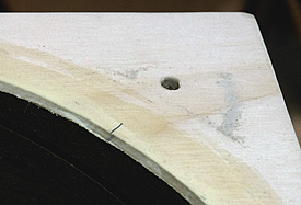
Pencil alignment marks ensure that the focuser hole is properly oriented with the rear flange.
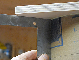
Using a carpenter’s square to confirm that the rear flange is perpendicular to the tube.
Both plywood parts are glued to the cardboard tube with wood glue — no nails or wood screws were used. The large holes in the ring and the flange were dimensioned so that the tube would fit snugly, but not so tight that a great deal of force would be needed to join them together.
Before the gluing operation, I made sure to complete whatever finishing was necessary for the plywood parts — it would be a lot more difficult to sand and drill holes in these pieces once they were attached to the tube. The other minor bit of prep was to use some sandpaper to rough up the outside of the tube where the plywood parts were to be glued. This was to ensure a good bond.
Once everything was ready, I applied a generous amount of wood glue to the inside of the ring and the outside of the tube, smearing it around with my finger. The ring slid on the tube with just a little force — the glue acting as a kind of lubricant. Once the ring was in position and flush with the end of the tube, I wiped up the excess glue with a piece of damp paper towel.
After the front ring had set, I repeated the gluing operation with the rear flange. There were a couple of minor complications to this task. First, I had to mate to the flange to the tube as close to perpendicular as possible. Second, I needed to make sure the focuser hole ended up where I wanted it — about 45° from vertical. A couple of pencil alignment marks took care of the focuser orientation issue, and a carpenter’s square helped ensure that the tube was perpendicular with the flange.
With the plywood parts glued in place, the tube is now complete and ready for painting.
Day 11: Balancing Act
The upper tube assembly complete with front ring and rear flange.
Now that the tube assembly is reasonably complete, the next step is to build the rocker box. However, before I can draw up plans for that, I need to find one critical parameter: the scope’s balance point.
Finding out where the optical tube assembly (OTA) balances is crucial for determining the height of the rocker box. While you can get a reasonable estimate of the balance point mathematically by weighing all the individual parts and noting where they’re positioned, I find it simpler and more accurate to put the tube assembly together. That means installing the optics, finder, focuser (with eyepiece), etc. — everything that will be in the final scope. Of course, you have to protect the reflective surfaces of the mirrors since you’ll be putting them inside an unpainted, saw-dusty tube.
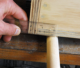
Measuring the location of the balance point. For my scope, it lies about 2¼-inches from the top of the mirror box.
Assembling the OTA for the first time felt slightly monumental — like a milestone had been reached. Sure, there’s quite a ways to go yet, but for the first time, what had been just a bunch of wood and cardboard was now actually a telescope. It was a nice moment.
Finding the balance point was pretty straight forward. I simply lay the OTA on a table with a length of wood doweling under it. (You can use a broom handle, or anything else that’s round and about 1-inch diameter.) I rolled the scope back and forth until I found the position where the OTA had an equal tendency to tip forward and backward. I then measured the distance from the top of the mirror box to the centre of the dowel, and voilà — I had my balance point.
Now it’s time to get out the paper and pencil and dimension the rocker box.
Day 11½: More Balancing
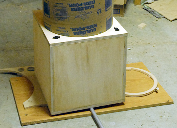
Using an aluminum pole to check the scope’s vertical balance.
Every once in a while the Perfection Gene takes over and I find myself modifying a design in ways that probably won’t make the slightest bit of difference to the telescope’s performance. Sometimes though, it’s more important to know it’s right, than for it to matter if it is.
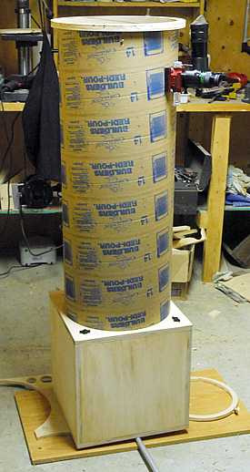
Shortly after posting Day 11, noted telescope maker Ed Jones pointed out that although my telescope was correctly balanced for when it’s aimed horizontally, it wasn’t perfectly balanced for when it’s aimed straight up. Ed correctly pointed out that because the finder and focuser are offset from the telescope’s vertical centre of mass, their weight would make the scope tend to want to move past the zenith when the scope is nearly vertical.
Because my scope is quite heavy, the offset weight of the finder, focuser, and eyepiece are proportionally tiny by comparison. Indeed, I could safely ignore this consideration — the friction in the bearings will easily be great enough to prevent the scope from moving on its own. (For smaller, less massive scopes though, the vertical balance issue needs to be addressed.)
The Perfection Gene started working on me, and soon enough I was back in the garage checking the scope’s vertical balance. My measurements show that to completely compensate for this factor, I would have to position the side bearings off centre, about ½ inch towards the finderscope side of the tube (the top, when the scope is aimed horizontally). The horizontal position of the side bearings would remain as measured before.
Moving the side bearings a small amount is easy, but it does add another parameter to factor in when I design my rocker box. Call it the price of perfection.
Day 12: Rocker Box Plans
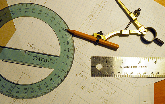
Careful planning minimizes frustration and waste — time spent with graph paper and drafting tools yields great rewards.
I’m a big believer in scale drawings. As I often say, you can’t make what you can’t draw. Sometimes, sketches are the only way to really figure out how to solve a problem. Other times, they provide a reality check to ensure you don’t make a mistake that only becomes apparent after you’ve cut wood and assembled the part.
Having built my scope’s OTA, I had all the dimensions necessary to plan the rocker box. But before I could tackle that part, I needed to figure out a few things:
1. How high should the rocker-box sides be to allow the mirror box to clear the rocker’s central pivot bolt?
2. How low does the front board have to be to allow the tube to aim horizontally?
3. How high can the rear piece be?
4. How much space should there be between the sides of the mirror box and the inside of the rocker box?
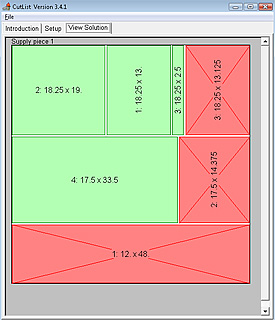
A layout diagram generated by Cutlist.
All these questions can be answered with a little thought, a pencil, and some graph paper. For example, I solved #1 by using the Pythagorean theorem, but I also got the same result (16½ inches) by making a scaled drawing. That gave me confidence that I had the correct answer.
Of course, the sides of the rocker box don’t need to extend all the way up to the centre of the pivot point on the mirror box. Why? Because the Teflon pads that support the side bearings on the mirror box are ideally positioned 70° apart, which means the parts of the rocker-box sides that extend higher serve no function. With my scope, I can trim the sides of the mirror box down to about 13-inches for a more compact configuration. Again, I was able to sort this out with a scale drawing and some simple math.
After a few drawings were completed, I had answers to all my questions and a parts list. The next step was to lay out the parts in a cut diagram. This task is made easier thanks to a nifty piece of software I found called Cutlist (version 3.41). You tell the program the dimensions of the individual parts and the size of the stock you’re working with, and the software lays out the pieces in the most efficient arrangement possible. There are several versions of Cutlist and I’m sure there are other programs out there that do the same thing, so Google “Cutlist” and choose one that suits your inclinations.
Day 13: Rocker Boxed
Five easy pieces make up the rocker box — all stacked in a neat pile.
One of the Dobsonian’s greatest virtues is its simple construction. For a scope like the one I’m building, two of the main parts are essentially boxes. But for each component there are a few construction tricks that help ensure that the resulting telescope works as it should.
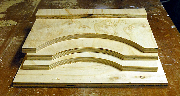
The rocker box is a 5-sided box with cutouts. Once you’ve decided on its dimensions, the only tricky part is cutting the curves where the side bearings will seat. Here, again, the router is our friend.
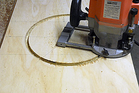
The two sides of the rocker box are still joined top-to-top while being routed.
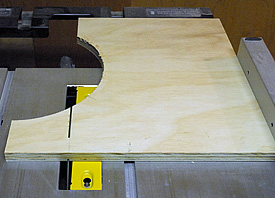
One side of the rocker being trimmed to height.
I find it very helpful to hold off cutting the rocker box sides until after I’ve first cut the curves for the side bearings. That way, instead of cutting arcs into two parts, you can cut a complete circle into a single piece of plywood.
This accomplishes two important things. First, it ensures absolute symmetry — the location and dimensions of the curves in both sides will be identical. This is important for ensuring the scope’s azimuth motion is smooth and even. Secondly, cutting one complete circle with a router is easier than setting up the router to cut two pieces. The only downside is that you produce a bit more scrap this way.
Making the rocker sides is a 4-step process. First, I cut a single piece to the required dimensions (basically, the width of the pieces and double the height). Second, I route a hole that corresponds to the diameter of my side-bearings, plus the thickness of the Teflon pads. Third, I cut the piece in half. And fourth, I trim the excess off the tops of the two side pieces. (You only need the sides to extend a little higher than where you plan on positioning your Teflon pads.) And just like that, I have two identical rocker box sides.
The front of the rocker also has a curve cut into it to allow the tube to aim horizontally. You could just make do with a board that goes straight across, but I prefer the extra rigidity and looks of this style. I used my trusty jigsaw and cut this arc freehand since accuracy isn’t crucial
Now it’s time for more gluing and screwing.
Day 14: Rocker Assembly
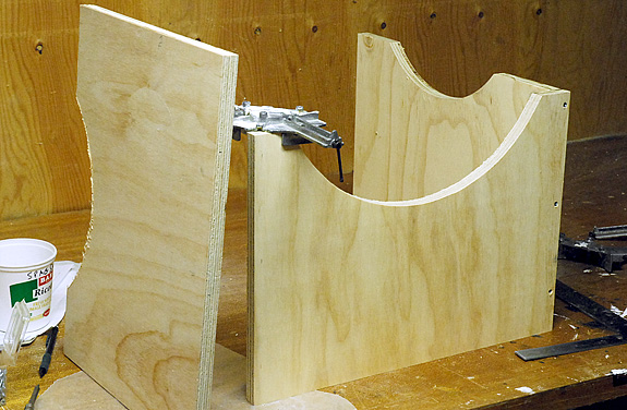
Clamping, gluing, and screwing the rocker box together.
Once the pieces have been cut, putting the rocker box together is easier than assembling Ikea furniture. At least you don’t have to deal with crumbly particle board and weird hardware.
The rocker box for this scope came together quite easily and the process was the same as for the mirror box. Again, the corner clamps came in very hand and lots of wood glue and Robertson-head screws were used. The main thing I wanted to be sure of is that the rocker box came out square. Since I dimensioned it so that there was only ⅛-inch clearance between the inside of the rocker box and each side of the mirror box, this was obviously important. I was pleased to see that when all was said and done, it looks as if everything came out fine.
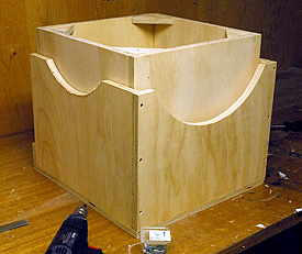
Thankfully, the mirror box fits inside the rocker!
Building the rocker box made me realize that over the years I’ve evolved a method of working that seems to suite my somewhat impatient temperament. I’ve completely separated the planning from the construction. In other words, when I go into the workshop, it’s strictly to work — not to think. All the thinking and planning happens in the calm and quiet of my office, usually well before I visit the workshop. This separation of tasks ensures that I don’t get distracted and that I think everything through before I start doing any cutting. Experienced builders will probably chuckle because for them this is probably standard operating procedure. None the less, on this project at least, it’s saved me considerable time and head scratching.
Jump to Week #3
Did you find this article interesting or helpful? If so, consider using this link the next time you shop at Amazon.com. Better yet, bookmark it for future use. Thanks to Amazon’s associates program, doing so costs you nothing yet helps keep this site up and running. Thanks!