
Remounting your Newtonian reflector’s primary mirror could lead to better performance and easier collimation.
Many telescopes have mirror mounts that are less than ideal. Some hold the mirror in place with clips that project over its surface and introduce image-harming diffraction effects. Others have adjustments that require tools or are so frustrating that observers rarely attempt to properly collimate the optics. Some cells effectively seal the mirror from the outside air. With no provision for ventilation, it is virtually impossible for the primary to cool down to the ambient air temperature — crucial for sharp images. Some mirror cells have all these problems!
This state of affairs is not only undesirable, but it is also completely unnecessary — a cell that properly supports the primary mirror, while allowing for easy collimation and good ventilation is not difficult to make.
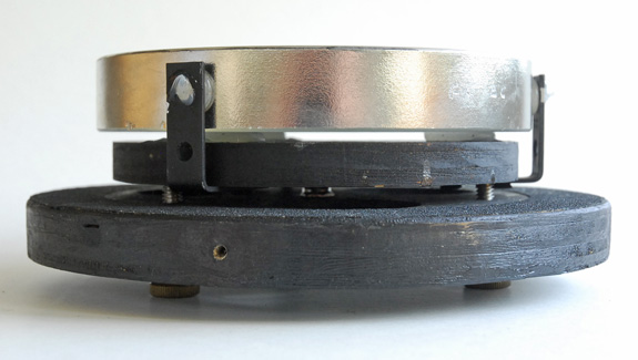
The cell described here is the same one I’ve used in most of my home-built reflectors. It is simple, yet provides easy adjustment for accurate collimation. Best of all, it can be adapted to just about any existing telescope, home-built or commercial. is easy to build and is suitable for normal-thickness mirrors (those with a diameter-to-thickness ratio of about 6:1) up to 10 inches diameter. The design is based on one described in Neale E. Howard’s Standard Handbook for Telescope Making and is one of a family of “double plate” mirror cells. The main components are two disks of plywood separated by a center pivot. Adjusting the three collimation knobs changes the tilt of the primary mirror. Because this design doesn’t use springs, it holds collimation better than many conventional cells. Why it isn’t more widely used is a mystery.
Construction Details
Begin by cutting a disk of plywood the same diameter as your primary mirror— this will be the mirror plate. I find that ½-inch-thick plywood works well for mirrors 6 inches and smaller, while ¾ inch is about right for larger mirrors. You don’t want the wood to be too thin or it may flex enough to distort the precise optical figure of the mirror. Next, using ¾ inch plywood, cut another disk that measures 1/16 inch less than the inside diameter of your telescope tube. This will be the tube plate. An ordinary jigsaw does a fine job at cutting circles, either freehand or with a circle-cutting jig, but a router produces the cleanest cuts.
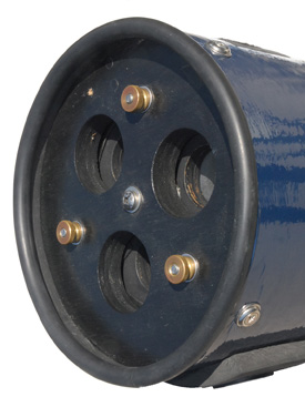
Drill ¼-inch holes through the centers of both disks and temporarily bolt the pair together. This will ensure that the rest of the holes you drill will be accurately aligned. It’s also a good idea to mark the disks in some way so that you can line them up again later with the same orientation. Next, use a hole saw to cut three evenly spaced ventilation holes through both disks. The holes should be as large as you can make them without weakening the structure of the cell. For the cell of a 6-inch mirror, I use 1½-inch diameter ventilation holes, but in my 8-inch scopes they are 2 inches across.
Now drill three equally spaced ¼-inch holes through both pieces of wood. Position these about ¾ inch from the outside edge of the mirror plate. Countersink these holes on the side of the mirror plate on which the primary will sit. Separate the disks and give them a coat of flat-black paint. I find that Krylon Ultra-flat spray paint gives a nice dull finish and dries very quickly.
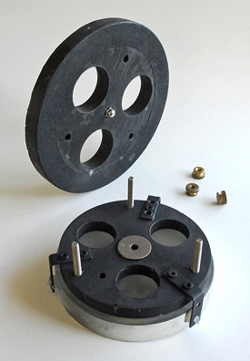
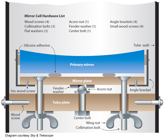
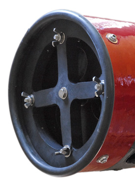
To complete the mirror plate, attach three angle brackets from the underside so that there is about a ⅛-inch gap between the bracket and the edge of the mirror. As the diagram shows, you will want to choose a bracket size that comes up nearly even with the front surface of the mirror. Run three flat-head ¼-20 bolts through the plate and secure them in place with nuts and washers. (Alternatively, you could make the bolt holes slightly undersize and thread the bolts directly into the wood, thus eliminating the need for the nuts. This is the method I usually employ.) These will be the collimation bolts and will have to be long enough to pass through both plates with about ½ inch extra. If you’re using ¾-inch plywood throughout, you will need bolts at least 2 inches long. Last, epoxy a ¼-inch fender washer to the center of the back of the mirror plate. This will provide half the pivoting mechanism for the cell.
The tube plate itself requires only a little work. Begin by enlarging the three collimation bolt holes — make them about 5/16 – to 3/8-inch diameter to minimize the chances of the collimation bolts binding. Next, insert a ¼-20 bolt (1 inch long if you are using ¾-inch plywood) through the center hole into an acorn nut, which bears against the washer on the back surface of the mirror plate and provides the pivoting action necessary for collimation. Finally, drill four equally spaced pilot holes in the side of the tube plate. These will accept the wood screws that hold the complete cell assembly in the tube.
Final Assembly
With the bits and pieces completed, it is time to assemble the cell. Paying attention to the registration marks you made earlier, join the two plates together so that the acorn nut and washer are in contact, and thread wing nuts (or hand knobs with threaded inserts) and washers on to the collimation bolts. These should be firm but not too tight — you don’t want to warp the mirror plate.
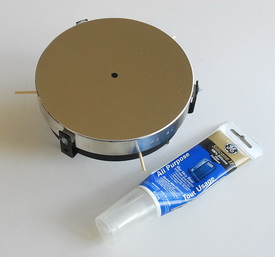
All that remains is to glue the mirror in place with silicone adhesive. The procedure is straightforward. Always start with a fresh tube of clear silicone adhesive. This material is readily available in just about any hardware store. It is also strong and flexible — ensuring that your mirror will be held firmly in place and effectively decoupled from the mechanical stresses of the cell assembly.
Before applying the adhesive, make sure that the back of the mirror is grease free and clean by giving it a quick wipe with solvent. Next, expose three equally spaced patches of bare wood on the mirror plate. (Silicone adhesive adheres better to wood than to painted surfaces.) I use a countersink tool to make small cups to hold the material. The ideal location for these is about halfway from the center to the edge of the cell, although the exact location isn’t terribly critical if your mirror’s thickness is about one-sixth its diameter.
To attach the mirror, lay three spacers down on the mirror plate between the glue points. Nails, skewers, even a stack of coins will work — just be sure you can remove them once the adhesive has set. Squeeze out three blobs of silicone onto the bare patches of wood. How much? You’ll want to use enough that the adhesive will spread out into disks about ¾ inch across when the mirror is resting on them, although this isn’t terribly critical either. About the only mistake you can make here is to smear too much on the back of the disk — you want the mirror to be supported on three evenly spaced pads. Now gently lower the primary mirror onto the cell. The mirror will come to rest on your spacers, and the silicone will spread out into tidy disks. Take care to gently position the mirror so that it is centered in the cell, and then leave the whole thing to cure undisturbed for at least 24 hours.
The last step in the process is to use a little more silicone between the side of the mirror and the brackets. This will provide lateral support and a measure of extra safety. However, you don’t want the mirror to be hanging from these contact points, which is why you should wait until the previous application of silicone has cured. Remove the spacers from beneath the mirror, and then squeeze some silicone through the screw hole in the brackets until it contacts the mirror and spreads out. (Make sure you don’t get any on the front surface of the mirror!) Again, let it set for 24 hours.
That’s it — you’re done. All that remains is to install the mirror and cell in the telescope tube and collimate the optics. Simply drill four holes that match the locations of the corresponding screw holes in the tube plate and drive wood screws through the tube and into the cell. If you’re replacing an existing cell, make sure that the face of the mirror winds up where it was originally.
For minimal cost and an afternoon’s effort, you will be rewarded with a mirror cell that is easy to collimate and lets your primary perform at its best.
Note: This is an expanded and updated version of article that I wrote for the May 2002 issue of Sky & Telescope magazine.
Did you find this article interesting or helpful? If so, consider using this link the next time you shop at Amazon.com. Better yet, bookmark it for future use. Thanks to Amazon’s associates program, doing so costs you nothing yet helps keep this site up and running. Thanks!